Frequently Asked Questions
Please find here the frequently asked questions (FAQ) in electronics production... The questions are categorized into topics below.
RoHS
Please see explanations about RoHS.
Restriction of Hazardous Substances Directive 2002/95/EC ( RoHS 1 ) is the abbreviation of the Directive on the restriction of the use of certain hazardous substances in electrical and electronic equipment . It was adopted by the European Union in February 2003.
English R estrictio the o f H azardous S ubstances Directive (Restriction of the Use of Certain Hazardous Substances) consist of the first letters of the word.
The RoHS directive came into effect on July 1, 2006 and is required to come into effect and has become law in every member state. This directive (with exceptions) restricts the use of ten hazardous substances in the manufacture of various electronic and electrical equipment. It is closely linked to the Waste Electrical and Electronic Equipment Directive (WEEE) 2002/96/EC (now superseded<>), which sets collection, recycling and recovery targets for electrical products and is part of a legislative initiative to address the problem of large volumes of toxic electronic waste.
Lead-Free Soldering Alloys
Please see all questions concerning Lead-free soldering alloys.
This phenomenon is mostly seen with all lead-free alloys. Gas escape to the outside causes bubble formation on the solder joint surfaces. There is no definitive reason for this phenomenon, although some suspected causes include:
Finish on the pads: This is more visible on ImAg surface finishes, especially those with high organic content.
Flux trapped in volatile materials.
Poor coating on PTH.
Lead-free has a lower density than Sn/Pb so any volatile gas is less buoyant in lead-free. (Lower power pushing the gas out)
Rework Stations
Please see all frequently asked questions about Rework Stations.
1) Low Temperature Soldering :
High-power, integrated heaters, tips and the lowest on the market with thermocouple temperature soldering iron and repair station.
2) Read & Feed :
U extending copper wire is used for this. Thermocouple and heater element is a combination of the two is microprocessor controlled. 140wattlık work with 60 Hz per second with a transformer. Therefore, thermal performance is unbeatable.
3) Starting temperature :
10 to 90 seconds to reach 360°C in a conventional system. Only 2 seconds to reach this temperature Any JBC station.
4) Long-Life End : soldering iron is left is left to stand, the tip temperature is automatically reduced to 200 ° C. Thus, oxidation and corrosion is reduced. Compared with the conventional tip 3-5 times longer it means life. When the temperature is reached immediately taken from the soldering iron stand again.
Note: the tip geometry, temperature setting, solder, flux and vary depending on the wearer but generally between 25,000 and 100,000 solder joints can be created.
5) Change Quick Tip : There is no need for any tools to change the tip. Just place the holder, pull and insert the new tip. Quick tip changes reduce lost time.
6) Ergonomic Design : The JBC lightest available, they are the smallest and most ergonomic soldering iron.
7) Process Control : Take control of your process in your hand! Set temperature limits, read counters, lock the station with a PIN code or key against unwanted use.
8) Intelligent Thermal Control System :
Extend tip life by reducing temperature and energy use. It consumes only 4 watts in sleep mode.
9) Easy Calibration :
JBC technology is microprocessor controlled because there is no need to recalibrate any of the JBC stations. If desired, however, it can be easily done using the soldering tip TI2800 thermometer calibration.
10) High Efficiency : According to JBC soldering station technology with the best performance on the market 80% more efficient. In the following graphs, based on practical tests show this superiority.
The time to reach 350 °C
The graph below shows the performance of heating, competing with JBC soldering.
Result
JBC has fast thermal response irons on the market.
Process for 3 solder joints
The chart below shows the performance of the 3-port row to the same device. Thermal reaction at a temperature of 70° C than competing devices falling due to the weak, JBC also experiencing falling only 30°C. Soldering difference increases even more open.
Result :
Equipment JBC soldering at 350°C can effectively, can rival devices
BGA Rework Stations
Please see below for all questions asked concerning BGA Reworks Stations.
Life would be much easier if, as an engineer, we made purchasing decisions based on a single factor. For example, the one that offers the highest electrical power. Unfortunately, real life is not like that. To understand what these powers mean, you have to take a closer look. If we take a hot air system with a 2.4kw top heater and compare it with PDR's 150w Focused IR system, you may think you have made up your mind right away. However, these figures may mislead you about the heat actually reaching the component.
The power of hot air systems must be higher than a PDR system so that it can compensate for the losses in the transition from heating element to component. If the PDR system increased its power to 2.4kw, the IR heater would probably burn a hole not only in the PCB but also in the table!
Solder Paste
Please find out all fequently asked questions regarding solder paste.

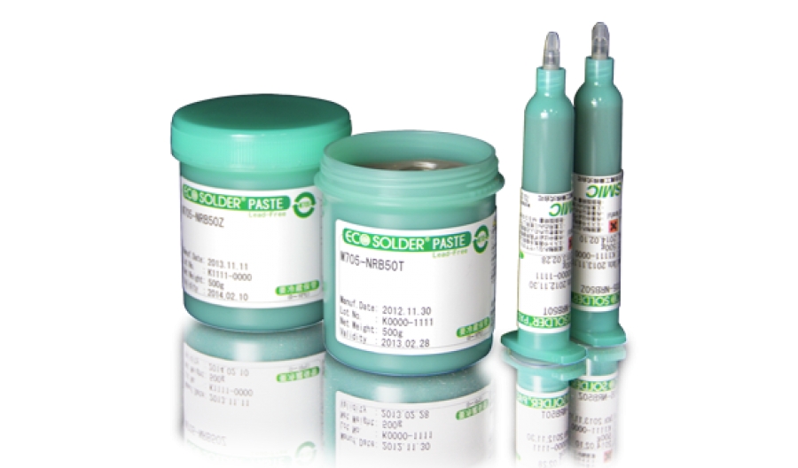
Solder paste is a mixture of solder spheres held within a specialised form of solder flux. As the name indicates it has the texture of a paste, and hence the name.
The fact that it is a paste means that it can be easily applied to the board during PCB assembly.
The solder particles are a mixture of solder. Traditionally this used to be tin and lead, but with RoHS legislation has been introduced around the world, to only use lead-free solders. These may be made from a variety of mixtures. One is 99.7% tin and 0.3% copper, whereas there are other mixtures that include other metals including tin.
Soldering Iron
Soldering irons, how to use soldering irons, tips and etc... Please see them all below.
To determine the soldering iron tip life is very difficult. But with a good use, life will be much longer. If cleaning sponge is too wet, the soldering iron tip which is 350 °C, will suddenly drop to 100-150 ° C. By time, these temperature drops crack exterior cover and melts the copper inside. In this case, the tip life is even shorter than 1 week. (Thermal Shock)
Extra heated ends (such as at 400-450°C) quickly becomes unavailable. Heat must be set to minimum so that workflow is not disrupted. Such as 350 °C (High Temperature)
The material cleaning the soldering iron tip end (iron, tin) must be of a softer material. It must be made of brass so that the tip is not damaged by friction. (Soft Cleaning Wire)
The amount of flux in the solder and flux used should be minimal. Because flux contains acid and is one of the most important factors affecting the life. We do not recommend to use resin paste. Although it makes soldering easier, because of maximum acidity in these products it pierces the soldering tip. Then one must do the cleaning. The residue left may lead to a short circuit in the future.
In the images below, please see how does it melts the solder iron tip because of the excess amount of flux.
Stencil
Stencil selection, design, cleaning and unders stencil cleaning and etc... Please see below regarding all these.
Under stencil cleaning rollers ensure that the screen of solder paste printing machines are kept clean and work efficiently, in other words, it is the cleaning roller for the bottom of the printing screen.
They are non-woven materials with a high durability rate, which do not leave dust and similar residues behind, are also suitable for vacuum cleaning and have a very high suction permeability, which are used for cleaning solder paste residues and other dirt-causing substances after solder paste printing. It can also be used wet or dry according to preference.
The machines suitable for the use of under-screen rolls are mainly ASM DEK and many other global brand machines and are available in different sizes according to demand. 400mm, 510mm and 600mm are the most preferred 3 types of under-screen rolls and you can view the length details of these rolls from the table below.
Model 1: 530mm x 510mm (53cm long)
Model 2: 530mm x 400mm (53cm long)
Model 3: 622mm x 600mm (60cm long)
Roll Type Main Width (A) Fabric Width (B) Roll Diameter (C) Inner Diameter (D) Roll Length (F)
400mm roll 530 mm 400 mm 56 mm 19 mm 10
510mm roll 530 mm 510 mm 56 mm 19 mm 10
600mm roll 622 mm 600 mm 56 mm 19 mm 10
You can examine the technical specifications of our high quality under stencil rolls that Assemcorp offers for sale below.
Main Components: 45% polyester, 55% cellulose
Weight: 68 g/m2
Thickness: 0.29 mm
Test and Inspection
Please see below for test and inspection issues.

With non-magnetic probes:
Accurate, reliable and repeatable measurement is provided.
Supports typical navigation applications on smartphones or special navigation devices.
Used for test applications where normal probes disturb the magnetic field.
Can measure three-axis movement without being affected by the test probe.
Soldering
What is "Soldering"? ... and many more questions about "Soldering".. Please find out here.
We recommend starting at 255°C for a single side and 260°C for PTH. In general, wetting performance decreases as alloy temperature decreases.

Printed Circuit Board (PCB)
Please see below for frequently asked questions about printed circuit board (PCB).
FR-4 (or FR4) is a grade designation for glass-reinforced epoxy laminate material. FR-4 is a composite material composed of woven fiberglass cloth with an epoxy resin binder that is flame resistant (self-extinguishing).
"FR" stands for "flame retardant", and does not denote that the material complies with the standard UL94V-0 unless testing is performed to UL 94, Vertical Flame testing in Section 8 at a compliant lab. The designation FR-4 was created by NEMA in 1968.
FR-4 glass epoxy is a popular and versatile high-pressure thermoset plastic laminate grade with good strength to weight ratios. With near zero water absorption, FR-4 is most commonly used as an electrical insulator possessing considerable mechanical strength. The material is known to retain its high mechanical values and electrical insulating qualities in both dry and humid conditions. These attributes, along with good fabrication characteristics, lend utility to this grade for a wide variety of electrical and mechanical applications.
Grade designations for glass epoxy laminates are: G-10, G-11, FR-4, FR-5 and FR-6. Of these, FR-4 is the grade most widely in use today. G-10, the predecessor to FR-4, lacks FR-4's self-extinguishing flammability characteristics. Hence, FR-4 has since replaced G-10 in most applications.
FR-4 epoxy resin systems typically employ bromine, a halogen, to facilitate flame-resistant properties in FR-4 glass epoxy laminates. Some applications where thermal destruction of the material is a desirable trait will still use G-10 non flame resistant.
Printing Defects
Please see below answers concerning your printing defects.
Under stencil cleaning rollers ensure that the screen of solder paste printing machines are kept clean and work efficiently, in other words, it is the cleaning roller for the bottom of the printing screen.
They are non-woven materials with a high durability rate, which do not leave dust and similar residues behind, are also suitable for vacuum cleaning and have a very high suction permeability, which are used for cleaning solder paste residues and other dirt-causing substances after solder paste printing. It can also be used wet or dry according to preference.
The machines suitable for the use of under-screen rolls are mainly ASM DEK and many other global brand machines and are available in different sizes according to demand. 400mm, 510mm and 600mm are the most preferred 3 types of under-screen rolls and you can view the length details of these rolls from the table below.
Model 1: 530mm x 510mm (53cm long)
Model 2: 530mm x 400mm (53cm long)
Model 3: 622mm x 600mm (60cm long)
Roll Type Main Width (A) Fabric Width (B) Roll Diameter (C) Inner Diameter (D) Roll Length (F)
400mm roll 530 mm 400 mm 56 mm 19 mm 10
510mm roll 530 mm 510 mm 56 mm 19 mm 10
600mm roll 622 mm 600 mm 56 mm 19 mm 10
You can examine the technical specifications of our high quality under stencil rolls that Assemcorp offers for sale below.
Main Components: 45% polyester, 55% cellulose
Weight: 68 g/m2
Thickness: 0.29 mm
Wave Soldering
Please see below to find out more about Wave Soldering.

Printed circuit boards (PCBs) are often wave-soldered. However, some conditions make wave soldering difficult or expensive. Let’s take a look at the difference between wave and selective soldering.
Wave Soldering
Wave soldering is a bulk process where PCBs are passed over a wave of molten solder to attach through-hole (THT), surface mount technology (SMT), and mixed assemblies to circuit boards.
The major downside of wave soldering is the limited ability to define process parameters, which leads to poor solder joint quality and diminished product reliability. This limitation forces a one-size-fits-all approach to application and makes selectivity impossible. Solder washes over the board, applied universally, even where it is not required.
Additional, wave soldering disadvantages include:
High solder consumption
High flux consumption
High power consumption
High nitrogen consumption
An increase in post-wave solder rework
Masking of sensitive areas on PCB assemblies
Cleaning of wave solder aperture pallets or masks
Cleaning of soldered assemblies
With these significant disadvantages, wave soldering operating costs can be significantly higher when compared to selective soldering.
Selective Soldering
Selective soldering, also known as mini-wave soldering, offers cost-effective, repeatable results for THT and mixed technology soldering applications. Soldering points are individually programmed and monitored to control flux volumes and soldering time. And it is the only reproducible method for soldering THT components on a two-sided PCB assembly.
Selective soldering typically consists of three stages:
Fluxing or the application of liquid flux.
Preheating of the PCB assembly.
Soldering with a site-specific solder nozzle.
Selective soldering makes it possible to solder a wide range of PCB assemblies with advantages, including:
Secure and fast process optimization
Reliable solder joint creation without overheating components
Guaranteed process repeatability
The elimination of expensive wave solder pallets
The ability to solder around tall parts with tight spacing
The ability to solder dense concentrations of THT pins
All Nordson SELECT solutions come standard with nitrogen inerting, a titanium solder pot to resist the corrosive effects of aggressive lead-free solder alloys, and intuitive system software you can set up in minutes without prior experience.
Why Nordson?
You can be confident when choosing Nordson as your selective soldering partner. Our commitment to innovation, investment in R&D, and customer service excellence allow us to deliver consistent performance and reliability.
Download the Wave vs Selective Soldering Process Comparison Guide for additional process and cost information.
Hand Soldering
Please see following for frequently asked questions about hand soldering.
Brass wool: Although less aggressive than the Inox Wool, it is easily subject to deterioration. It will cause metal particles and fibers to contaminate the working area. Customers have refused to use Brass Wool for this reason. Brass wool was first used in industry many years ago and it became standard use in industry and was used by many operators.
Inox Wool: It is more agressive than the Brass wool and so will require more care when being used. It is the most effective when used less aggressively and therefore minimizing the abrasions – Remember! Less Is Better. As well as being more effective, Inox is much more durable than Brass. It is more flexible, less fragile, and as a result, reduces the amount of particles and contamination of the work area. In tests we found it very resistant to breakage and it contained less than 10 times the amount of broken particles than in Brass wool.
ESD
Please find out more info about ESD.
ESD stands for english words "Electrostatic Sensitive Devices" or "Electro Static Discharge".
SMT
What is SMT? You can find all the answers concerning your SMT related questions.
SMT is the abbreviation of the initials of the English words "Surface Mount Technology".
The production technology that uses surface mountable electronic components is called Surface Mount Technology. Before the use of surface mount elements, which are abbreviated as SMD to represent the initials of their English meaning, circuit assemblies could only be made with pinned circuit elements. Surface mount elements can be manufactured in much smaller sizes than pinned elements. Serial SMDs can be assembled with machines that include assembly robots. In this way, it is possible to design serial production and more miniature electronic circuits. Pinned circuit elements must be soldered by inserting them into holes in electronic cards and dipping them into a molten solder chamber, while SMDs are mounted directly on the card surface and then baked. The smallest chip component currently available in the industry is 008004 Size (0.25 x 0.125 mm). While small chips are mostly used only in devices that require high technology and require a small footprint (especially mobile phones, handheld computers, RF modules, etc.), it is possible to see larger SMDs in all types of electronic devices produced with surface mount technology.
Conformal Coating
Please find out all fequently asked questions regarding Conformal Coating.
What will the PCB’s Operating Environment be?
Coatings are applied in order to protect the PCB from corrosion in its operating environment. It is important then to consider the coatings ability to protect the board from its environment. The main questions which should be considered are:
- What temperature range will the board be exposed to?
- How rapidly will the operating temperature change (see thermal shock)
- What humidity will the board be operating in?
- Is condensation a consideration?
- Will there be salt present?
- Will it be immersed in water?
- What solvents will be present?
- What will be the level of UV present (daylight exposure)?
The coating must be suitable for use under the required operating conditions. Technical data sheets (TDS) are provided based on a range of internal and external tests according to international standards. Tests must also take place to ensure that the coating retains all the required properties throughout the duration of use. This is due to the differing conditions exhibited as a result of varying PCB materials and designs.
In addition to the performance characteristics of the cured coating, the application process plays an important role in the success (or otherwise) of the coating application and the following considerations should be made during the selection process:
Cure time available
Maximum cure temperature possible
Volume of boards to be produced
Available cycle time or TAKT time
Existing application equipment or new process?
What are the Electrical Requirements?
Conformal coatings form a protective, insulating layer. The most common electrical parameter tested is the Surface Insulation Resistance (SIR). This measurement is often taken before and after coating and exposure to harsh conditions, thus ensuring the coating continuously provides the level of insulation required. The coating should also exhibit high dielectric strength; the minimum required can be determined from the intertrack separation and the potential difference between adjacent tracks.
What will the PCB Board Layout be?
The design of the board should include consideration of the placement of components that should not be coated. Selective spray equipment or the application of a peelable coating mask can be used to help avoid such areas. Alternatively, gel materials can be used to form a ‘dam’ to contain the coating and avoid capillary effects transferring material to unwanted areas, such as connectors. Another aspect to consider is how close together the components are. If there is not sufficient gap between the components, it can lead to the coating bridging the gap rather than correctly conforming to the board, this can have a number of effects including the coating building up to become too thick and crack, or it can leave pockets under the coating where solvent can gather and cause corrosion.
Will it require Rework and Repair?
If the assembly requires repair then consideration must be given to the ease of removal of the coating. Electrolube offer products for the effective removal of conformal coatings, including those that are solvent resistant.
Removing Conformal Coating
Electrolube have a number of complementary products to assist with the removal of the coating, please see the section of the website here:- along with the TDS instructions.
What will the volume of production be?
The volume of production will have effect on a multiple of the other considerations mentioned in these articles. The most obvious being the application method and the cure times, for example automated applications will be preferable for mass production, whereas hand spray coating can be used on small runs.
What will be the final enclosure be like?
The mounting of the board in its final position can have an effect on the effectiveness of the coating for a number of reasons – for example, if the housing is open it will let more environmental elements in than a fully enclosed case. Whether the board is mounted horizontally or vertically is also very important, if possible it should be mounted vertically to avoid moisture from condensation sitting on the board.
Electronic Terminology
Frequently used Electronic Terminology and their meanings ...
An original equipment manufacturer (OEM) traditionally is defined as a company whose goods are used as components in the products of another company, which then sells the finished item to users.
Have Another Question?
Please share your contact information with us. Our customer representatives will respond as soon as possible..


